RF components such as couplers, filters, splitters, and antennas are used in cell phones, base stations, wireless consumer electronics, satellite components, and more. These products increasingly use broadband and multiband technologies for their operation and the accurate simulation of broadband performance is key to validating and optimizing RF product design early in the development process and reducing time-to-market.
CST Studio Suite® electromagnetic simulation software allows users to accurately model broadband technologies dispersion for product designs operating near or below the specified frequency using a built-in material library. For products that require broadband performance at higher frequencies than specified in the material library, CST Studio Suite provides the ability to easily upload broadband material data for more accurate broadband simulations.
This blog will focus on best practices for sourcing and defining broadband dielectric data to be added to the CST Studio Suite material library, as well as how to increase its fit accuracy, for simulation results that reflect the real-world broadband performance of your RF component designs.
Material Library in CST Studio Suite
CST Studio Suite includes an extensive material library with common metals, natural materials (air, mica, paper, etc.), and commercial materials. All of these materials come pre-defined with attributes required for electromagnetic simulations.
The most important attributes for the accurate simulation of dielectric material are the dielectric constant (Dk) and the dissipation factor (Df). These values relate to the permittivity and loss of material. While some manufacturers provide datasheets with a broadband material characterization, most datasheets specify a dielectric constant and a dissipation factor for a single frequency, for example, 10GHz.
These attributes work well if your design operates near or below the specified frequency. However, there are an increasing number of products, such as mmWave 5G, that require broadband performance at higher frequencies.
The benefit of using broadband data is increased accuracy for multiband or broadband RF designs on the same substrate. Broadband material data can be simulated by CST Studio Suite for accurate results across multiple frequencies using both frequency and time domain solvers. This ensures that you will have a good agreement between your simulations and prototypes, reducing your number of prototype iterations and time-to-market.
Sourcing Broadband Material Data
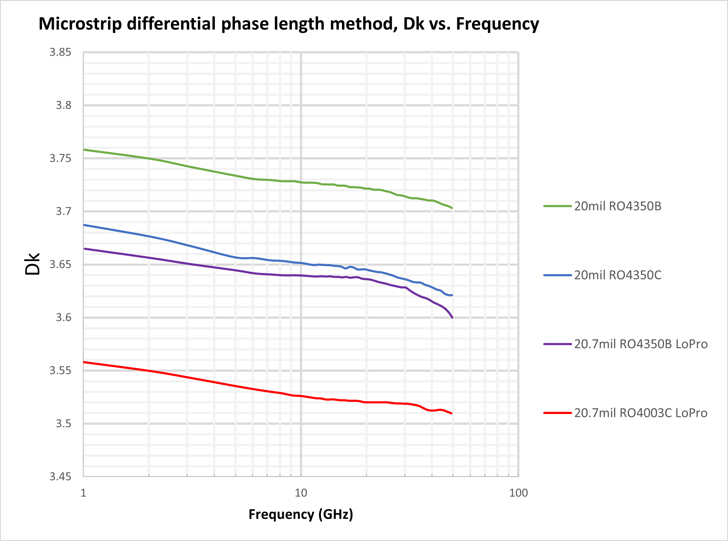
Most companies publish datasheets providing Dk and Df data. Let’s consider RO4350BTM laminates from Rogers Corporation as an example. This is a low-loss laminate with an advertised process dielectric constant of 3.66. is is an average number from several different tested lots of material and on the most common thickness/es as these parameters, together with frequency, conductor deposition and roughness can affect that value.
In the datasheet you may see that the actual Dk value for the RO4350B laminate with 20mil thickness and electrodeposited copper ranges between 3.75 near 1GHz and 3.7 near 50GHz, whereas the RO4350B LoPro® laminate version between 3.66 to 3.6. This is indeed a relatively stable value, but other substrate technologies can vary significantly more.
In a pinch, this data can be extracted from the datasheet using tools like WebPlotDigitizer. However, manufacturers will gladly supply you with this info if you reach out to their technical sales representatives. Rogers Corporation even has a free MWI tool that can be used to download the Dk-over-frequency values for all of their substrates. The tool allows selecting the substrate, its thickness and also other parameters such as the conductor roughness.
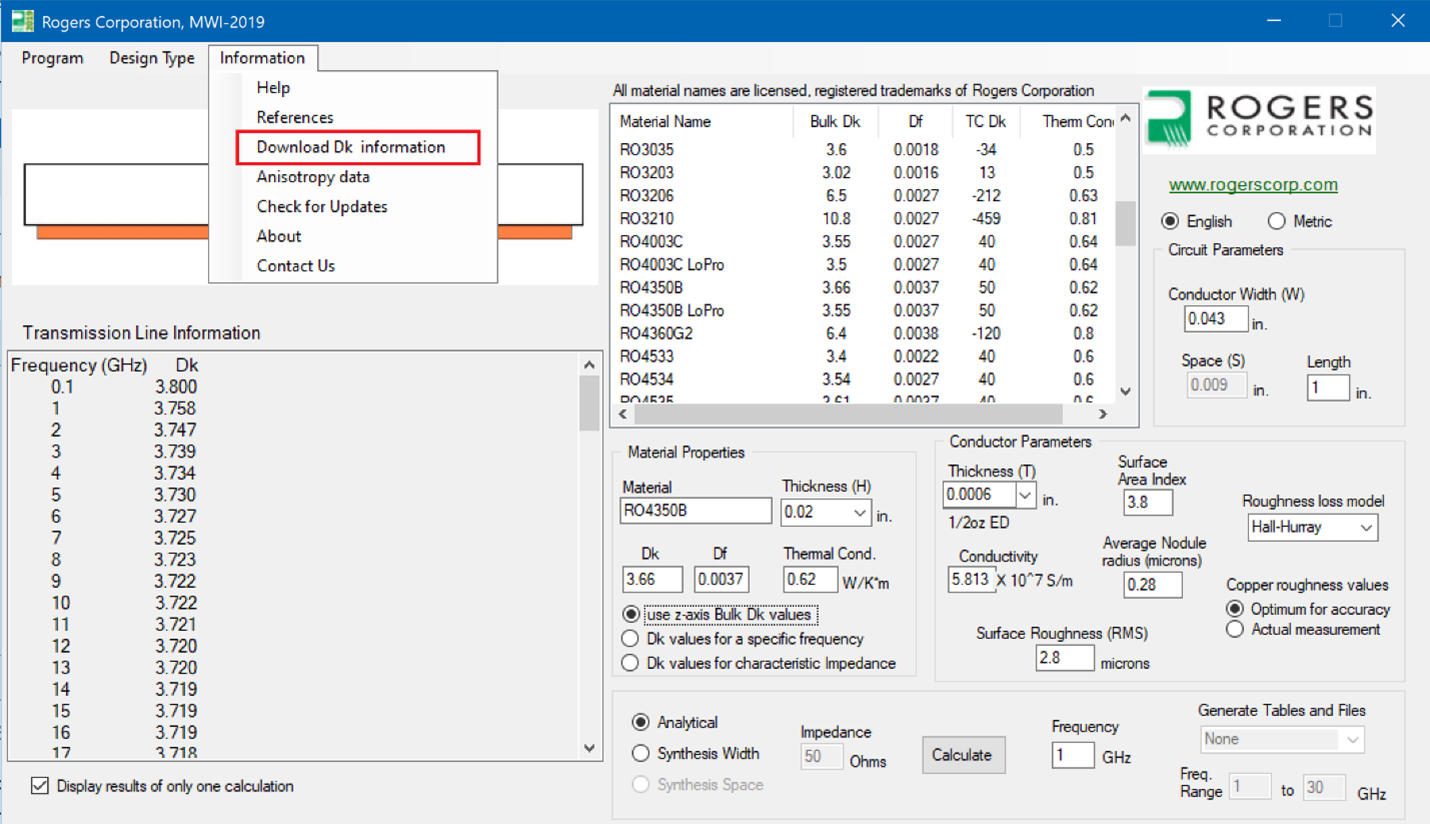
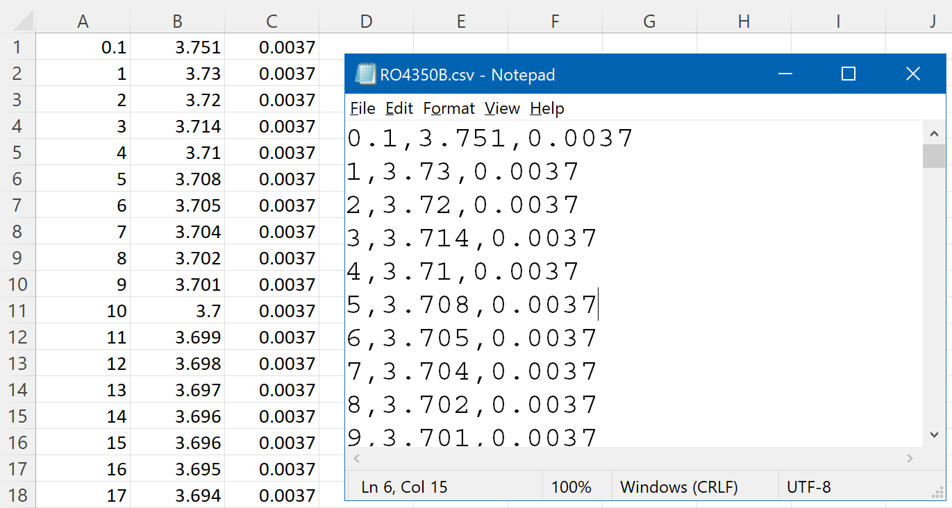
Once the Dk and Df data is obtained, it can be uploaded into a custom material and then stored in the CST Studio Suite material library for later reuse. The easiest way to do this is to first create a .csv file with frequency, Dk, and Df values. The Rogers MWI tool can generate a .xlsx file that you can easily convert to .csv, and other manufacturers can supply this data upon request.
Defining Broadband Materials
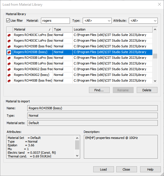
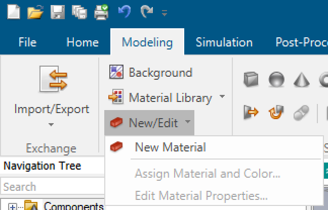
The following screenshots show how easy it is to upload this material data to CST Studio Suite.
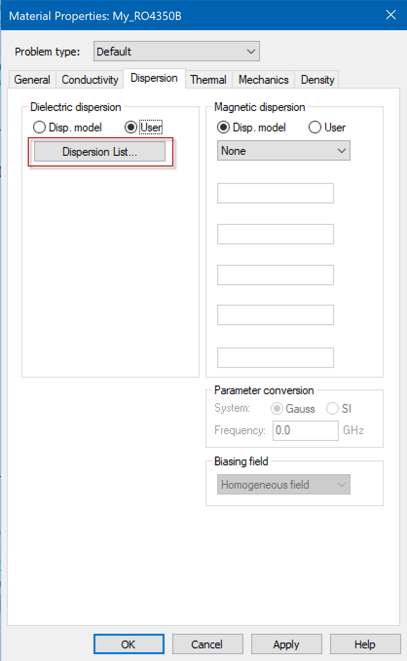

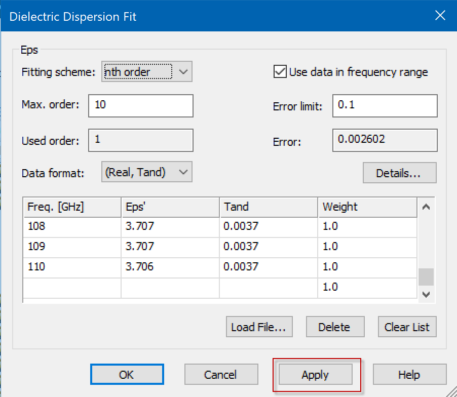
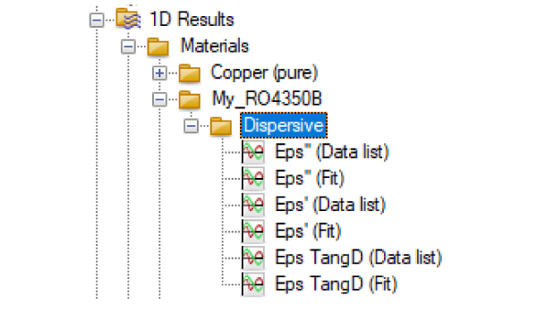
The target accuracy and maximum order for the pole-zero rational fitting algorithm are controlled in the corresponding fields in the dialog. You can then view the original data list and the fit curves in the 1D results folder. This will load immediately, independent of running a simulation.

How to Increase the Fit Accuracy of Imported Broadband Data
If you are using the frequency domain solver, CST Studio Suite will use the individual data points on the blue line that is shown in figure 10. To use time domain solvers a pole-zero rational fitting is required to use canonical transfer functions and to guarantee causality and passivity of the model.
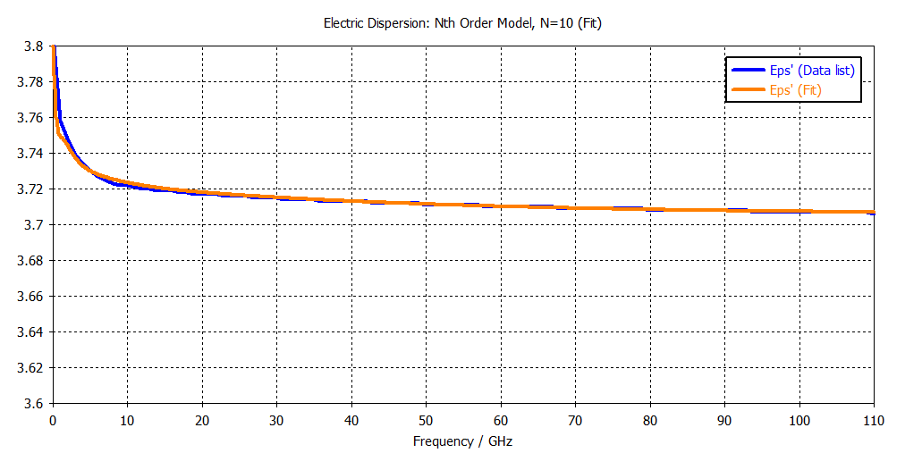
The fitting accuracy can be controlled in two ways. One is to decrease the error limit which could possibly enforce a higher-order fitting model. Note that a higher-order fitting can cause a longer simulation time. Here is an example of a 10th order fit:
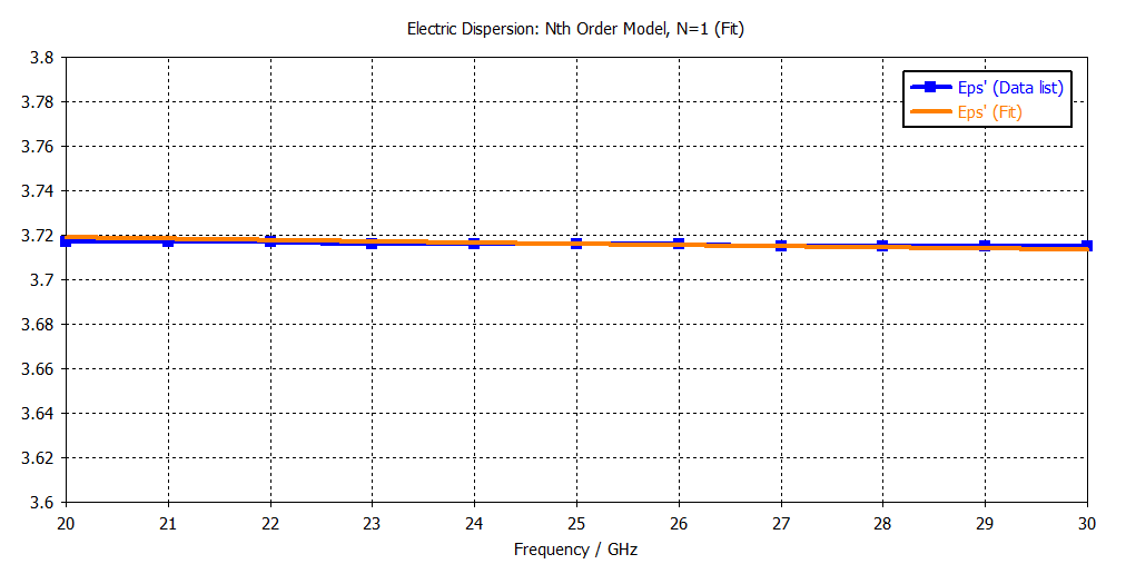
Another way to increase the fit accuracy is to limit the frequencies of interest in the simulation problem. If we were only interested in 20-30GHz, we would get the following high-accuracy yet low-order function (make sure to check “Use data in frequency range” in the dispersion fit table).
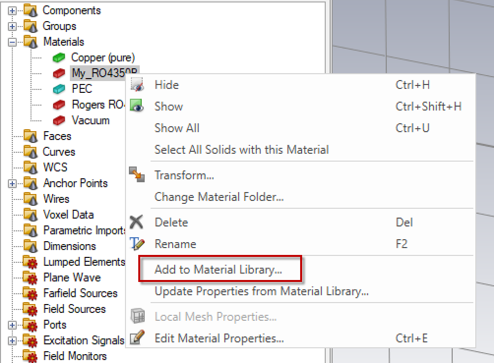
Once a satisfying fitting is obtained the newly generated material can be stored in the material library by right clicking on the material name in the tree and selecting “Add to Material Library…”.
Summary
CST Studio suite material library includes single-frequency and broadband manufacturer data. A little extra work is required to upload new models according to specific parameters such as layer thickness, conductor roughness, and deposition technology. This leads to an optimal material setup and ensures accurate simulations matching the real-world performance of your prototypes, allowing you to produce your products faster.
Questions?
If you have any questions or would like to learn more about how to define broadband material data in CST Studio Suite for the accurate simulation of broadband performance in RF component design, please contact us at (954) 442-5400 or submit an online inquiry.