
Sometimes, the motion of a mechanical system is simple enough that it is unnecessary to simulate it to validate product design before building a prototype. Mechanisms like latches or levers are easily represented in a 2D sketch or manipulated in the 3D space to get an accurate idea of the resulting movement. However, when the motion of a part or assembly is more complex, a designer would benefit from tools that can accurately portray the motion of the system to validate function early in the development process. This is particularly true when rapid prototyping is not an option due to cost, availability, or scheduling concerns.
With product design tools that simulate complex mechanical motion, users can prevent potential clashes and explore different position configurations to develop optimized parts and assemblies faster. Designers accurately predicting the motion and behavior of parts and assemblies enables companies to accelerate the production curve and shorten time to market, which is vital for attaining and maintaining a competitive edge. CATIA applications on the 3DEXPERIENCE platform allow for the creation of kinematic and dynamic constraints that generate these simulations.
For those unfamiliar with the 3DEXPERIENCE platform, design functions are grouped into apps which are then combined into “roles” that are offered to users. For example, the Mechanical Motion Designer role includes the “Mechanical Systems Design” and “Mechanical Systems Experience” apps, as well as others. These two apps are the focus of this blog as they pertain to the creation of kinematic and dynamic constraints to simulate motion.
Automatic Assignment of Kinematic Constraints
3DEXPERIENCE streamlines the creation of motion simulations by automatically assigning kinematic constraints while the designer assigns assembly constraints. This is a welcome improvement from CATIA V5 kinematics functionality, which requires constraints used in motion simulations to be generated independently by the designer.
Designers can seamlessly shift from the development of parts and assemblies and begin assigning motion based on existing assembly constraints. Furthermore, if revisions to parts and assemblies are required, the designer needs only to switch to the appropriate app to make the edits, which will immediately be available for incorporation into the motion simulation. This convenience reduces or eliminates the amount of time a designer may have otherwise spent importing and re-connecting updated parts.
In developing the assembly, a designer will place parts relative to other parts using assembly constraints, which are rules regarding the position of parts as they relate to others based on individual part geometries. As a user adds constraints, 3DEXPERIENCE will group the constraints between two parts into an “engineering connection”, which is the basis for assigning rules for subsequent use in motion simulations. For example, in this marble lifter machine, the designer will need to constrain the camshaft to the frame so that it will be able to rotate, allowing the cams to drive the motion of the lifters later when motion is assigned to the assembly. A “coincidence” constraint aligns the rotation axis of the shaft with the axis of the holes in the frame, while an “offset” constraint is used to place the camshaft in the correct position relative to the frame and is assigned a value of one millimeter. 3DEXPERIENCE recognizes this grouping of constraints as a “revolute connection”, wherein the shaft is constrained positionally in space but is free to rotate about its axis. An “angle” constraint is added to assist in the definition of the rotation of the camshaft.

Applying Assembly Constraint Modes
The assembly constraints have different modes available to the designer. The default is “driving” where the condition is required to be met, but to enable a motion simulation the designer will switch the mode to “controlled” and define an upper and lower limit, as well as a nominal value. The angle constraint in the marble lifter mechanism shown above is a controlled constraint, while the coincidence and offset constraints are driving constraints. Also available is the “measured” constraint which does not impose a condition on the assembly, but rather will output the result of the referenced features based on the driving and controlled constraints applied to the assembly.
Creating and Editing Assemblies in the Mechanical Systems Design App
In the Mechanical Systems Design app, the designer can create or edit assemblies. Once an assembly is sufficiently constrained and appropriate engineering connections are defined, a “mechanism” can be established, which enables the creation of the kinematic simulation. The mechanism applies the entirety of the engineering connections and allows the designer to move the assembly according to these rules and along the controlled constraints. This enables the designer to simulate motion and analyze the assembly in different position configurations.
Automating Motion in the Mechanical Systems
Experience App
In the Mechanical Systems Experience app, the motion simulation can be taken a step further by automating the motion. Once materials and weights are assigned, this motion simulation can even be used to anticipate loading conditions like force and torque applied at a given location. Additionally, probes can be assigned that will read the desired measurement as a condition of the system and will update dynamically as the assembly moves. Some things that can be measured with these probes are distance, angle, speed, acceleration, torque, and force.
Automating the motion requires implementing an “excitation”, found in the Mechanical Systems Experience app. An excitation works in conjunction with the controlled constraints created in the Mechanical Systems Design app. There are several types of excitations that are used to drive different kinds of motion depending on the desired effect.
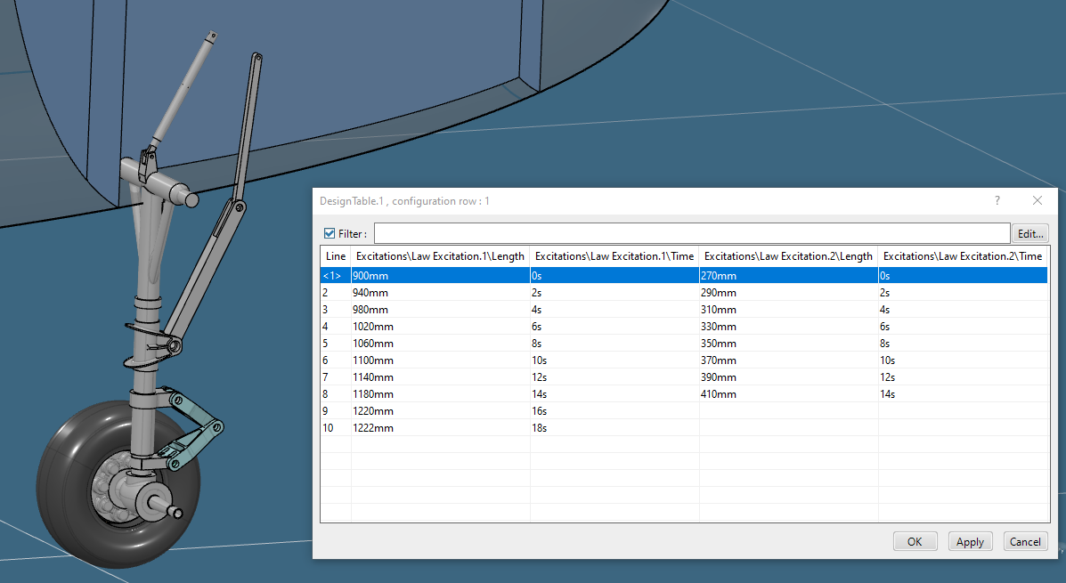
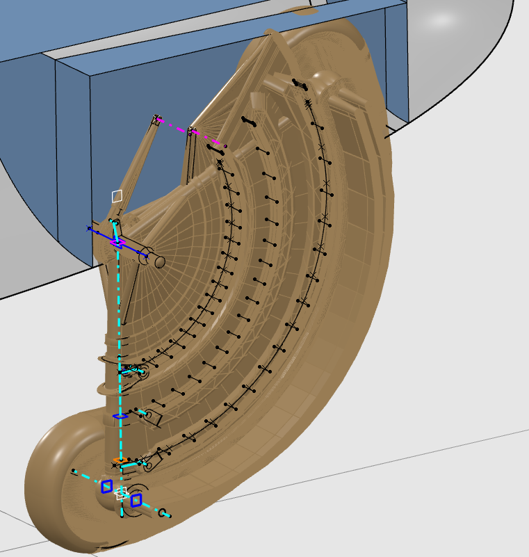
Looking again at the landing gear assembly, we can use a “law excitation” to drive the motion of the mechanisms created in the assembly. This allows us to direct the motion of the assembly according to a set of positions and at a certain time in the simulation. The table shown in the picture shows two excitations used to drive motion in the assembly. Notice columns two and four correspond with the command constraints and units are given in millimeters, while the third and fifth columns are the time markers given in seconds and are associated with the step numbers in column one.
In the marble lifter mechanism, a “position motor excitation” is used in conjunction with “gravity excitation”. The position motor excitation causes the camshaft to rotate, and the gravity excitation in combination with a contact constraint established in the Mechanical Systems Design app causes the lifters to move up and down. The marble itself is not constrained positionally at all and is allowed free movement driven by the gravity excitation and the contact constraint.
Adding Probes
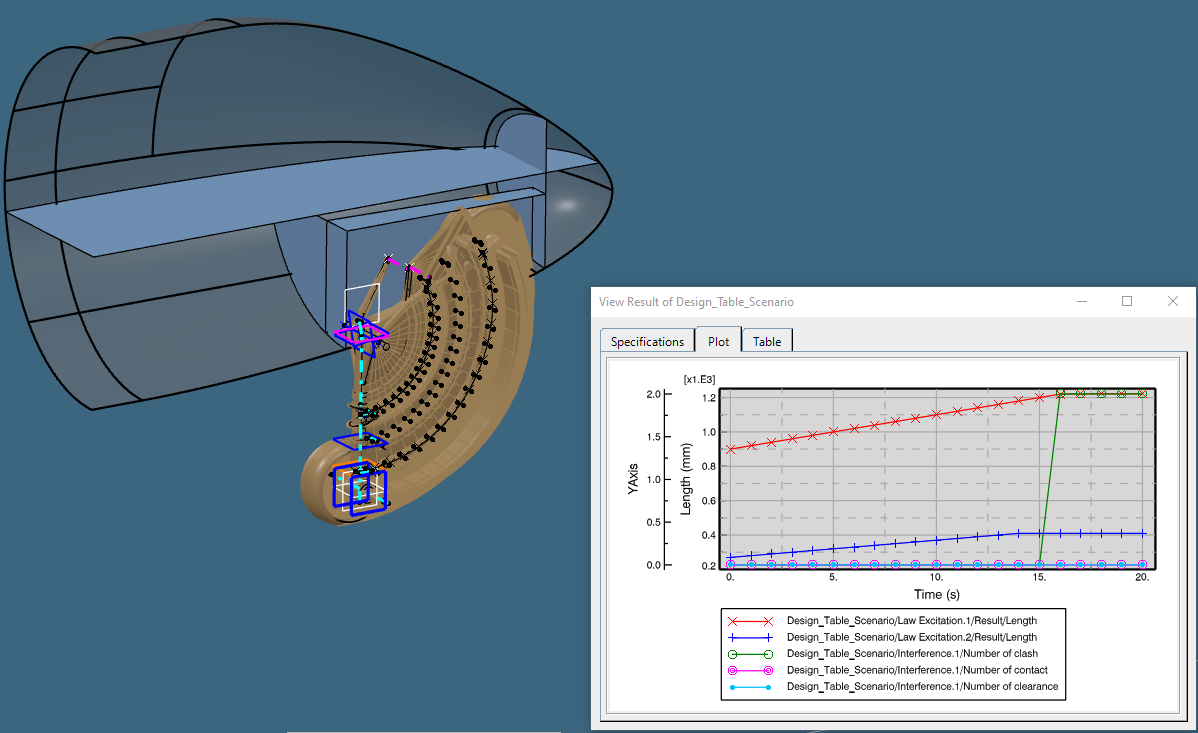
Below we see the effect of adding probes to measure things in the assembly, in this case, the distance between the tire and the fuselage and the angle between structural members in the mechanism. These measure probes can also be plotted for review, as shown below. We can assign and observe the motion from multiple angles using a “camera probe”, while interferences, contact, or clearance violations can be highlighted via an “interference probe”. A “section probe” can be applied to show the inner workings of the mechanism. Each of these is shown in the following video:
Viewing the Entire Assembly Motion
If the designer wishes to see the entirety of the assembly motion in one representation, a “swept volume” can be created to do just that. Each part’s path through space is represented in the sweep and is differentiated in the result. Additionally, a “trace” can be created to track a point as it moves with the assembly. These results can then be added to a product.
Questions?
If you have any questions or would like to learn more about simulating motion in CATIA 3DEXPERIENCE, contact us at (954) 442-5400 or submit an online inquiry.