Dassault Systèmes’ 3DEXPERIENCE Systems Traceability tool helps link heterogeneous systems together
Product development is a complex process and involves the use of multiple toolsets to conceptualize, design, build, test, manufacture, and service the product. While working in such a heterogeneous environment, the data not only needs to transition easily between these toolsets but there should be a clear way to trace the data as it passes through these various tools. The digital thread, or traceability, between heterogeneous environments helps users anticipate what systems will be affected when a change comes along.
The Dassault Systèmes 3DEXPERIENCE Systems Traceability tool helps link these heterogeneous systems together to build a system of systems model from a myriad of toolsets. Whether on the 3DEXPERIENCE platform or external to it, enabling systems analysis. Capturing the digital thread is key when using a Model-Based Systems Engineering (MBSE) approach. 3DEXPERIENCE Systems Traceability reduces product iteration loops by supporting collaboration and traceability in the extended enterprise.
The Value of Systems Traceability on the 3DEXPERIENCE Platform
The benefits of the 3DEXPERIENCE Systems Traceability app are:
- Provides a real time view of all the systems and analysis of a heterogeneous systems model in a single dashboard
- Enable compliance to stakeholders’ requirements at each step of the development process
- Analyze the end-to-end traceability links to easily foresee the implications of a change across systems and perform a thorough impact analysis of the change in a single view
- Provide visibility of relevant engineering data for better Project control: reveal engineering gaps
- Foster digital collaboration across the extended enterprise with a single view that includes external and legacy toolsets along with 3DEXPERIENCE data
How to Use 3DEXPERIENCE Systems Traceability
Systems Traceability Scope
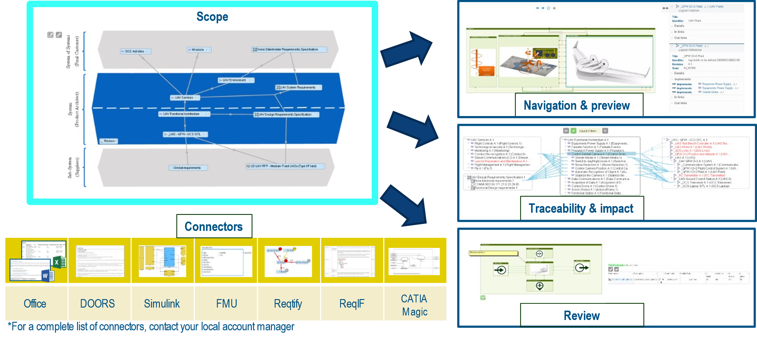
Analyzing the Systems Traceability starts with creating a Traceability Scope. This is like a project space that will contain the “systems” we want to work with. These can be 3DEXPERIENCE “systems” such as Requirements, Projects, Documents, Models, Analysis, Test Plans, etc. They can also be external “systems” such as CATIA Magic, DOORS, Jira, Simulink, etc. from which the information is accessed via connectors. When following the MBSE approach, an analyst can create multiple scopes to capture the decomposition of the system at conceptual to detailed level.
These systems allow users to view the underlying information and elements in the structure, which will be referenced during link creation and traceability analysis. The scope provides a centralized view and navigation on heterogeneous system engineering models from different authoring tools. If the tool is file based, then the user doesn’t require the application specific licenses to navigate and view the internal semantics of the models.
The example below is a scope that has the system architecture defined in CATIA Magic, requirements and component functional & logical behavior defined in the 3DEXPERIENCE platform. Software requirements & models defined in Word and Simulink.

Analysts can simply click on each system to do a deeper dive and view its content/models and properties within the Systems Traceability application. For CAD models, the 3DEXPERIENCE viewers can be used.

Once the scope is created, traceability channels (coverage) can be established by simply dragging the downstream system onto the upstream ones.
Computing Traceability and Creating Element Links
In the Traceability mode, we can analyze the system coverage and also create additional element links.
In our example below, the external systems do not yet have any element links between systems, hence the coverage is displayed as 0%:

By clicking on the percentage (%) bubbles, the analyst gets access to the coverage view. This provides a detailed view of each system’s elements and their connections to other systems in the scope. See below:
Analysts can create manual links by simply dragging an element in one system onto another:
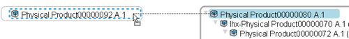
Patterns can be used instead to automatically create links between systems based on the pattern criteria.
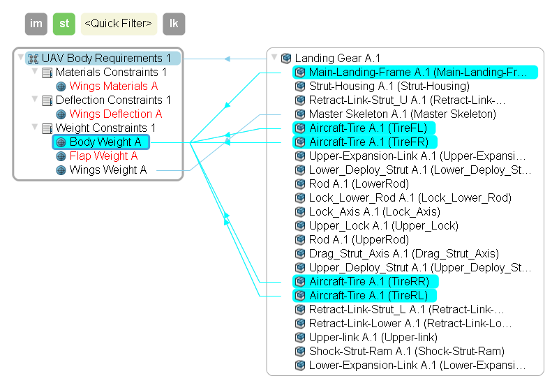
Once the links are created, selecting an element, will highlight a multi-level link. This is a key benefit when performing impact analysis of a system. User can easily understand the widespread impact of their change across multiple systems (on the platform or external to it) used during the entire product development process.
In our example, we can see how the reference requirement for Body Weight is in the CAD Model of the Landing Gear thus driving design constraints. The requirement is linked to the Sub requirement Weight in the Logical Model of CATIA Magic that was driven by the Conceptual Model. Thus, we can visually see the digital thread and analyze the impact to upstream and downstream systems if this requirement was to change.

We can export this information into a coverage table and download it as a spreadsheet for reference. The Coverage table below displays the connect from CATIA Magic to 3DEXPERIENCE Requirements and onto the CAD Model. This captures the thread from the conceptual MBSE model to a the Detailed level requirements and finally the detailed design.

The Analyst can also use the Matrix view to quickly check if links exist between systems or can create a link if none exist.
Revisions and Reviews
Systems are ever changing, and Systems Analysts can create a baseline of the entire scope with revisions. Say our stakeholder saves new requirements to the 3DEXPERIENCE platform. We can create a new revision of our scope and update the Stakeholder Requirement to the new Revision. We can reroute scope links automatically to point to the new revision.
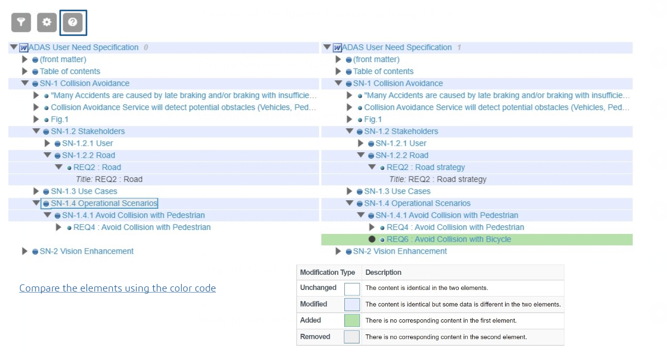
Analysts can also use the compare the 2 requirement revisions using the Difference table. This is especially useful if the system being tracked is a file such as Word or Excel and is being exchanged with external partners. In the below example, we can see for the requirement REQ2. The title has changed from Road to Road strategy. Also, a new requirement REQ6 has been added.
When working collaboratively on a scope, it is essential to have a way to leave review comments. Using the Review option, users can quickly provide feedback. Not only at the scope but in the individual systems as well as in the Coverage view.

Captures of responses to these reviews provide the history of the feedback cycle.
Questions?
If you have any questions or would like to learn more about , please contact us at (954) 442-5400 or submit an online inquiry.