Dassault Systèmes continues to listen to their customers’ needs and they’ve delivered many high-value CATIA Composites Design and Manufacturing enhancements in the latest releases of both CATIA V5 and CATIA 3DEXPERIENCE.
In this blog, we’ll highlight the Composites enhancements in CATIA V5-6R2021 and CATIA 3DEXPERIENCE 2021x that most current and potential users will want to know about, based on our composites support experience.
Other options to learn more about what’s new in CATIA Composites Design and Manufacturing include:
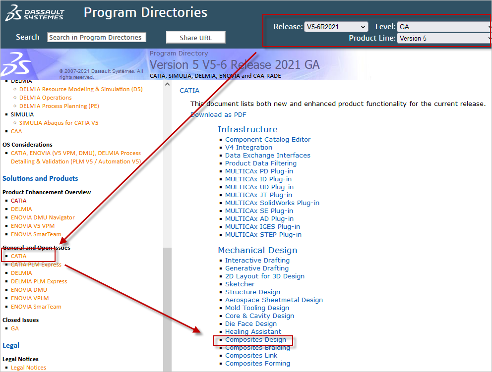
- Access the online CATIA Program directories, and review the complete list of enhancements on the “What’s New” page in the Composites Design workbench and other Composites sections. Contact Inceptra Support to assist with the setup if not installed.
- Contact your Inceptra Sales Manager or Inceptra Composites Engineer and arrange a personal presentation.
CATIA Composites Design & Manufacturing Enhancement Highlights for CATIA V5-6R2021 and CATIA 3DEXPERIENCE 2021x
Releases: CATIA V5-6R2021 GA / 3DEXPERIENCE 2021x
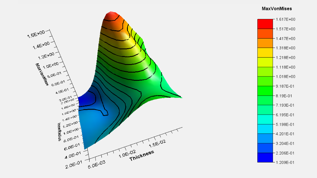
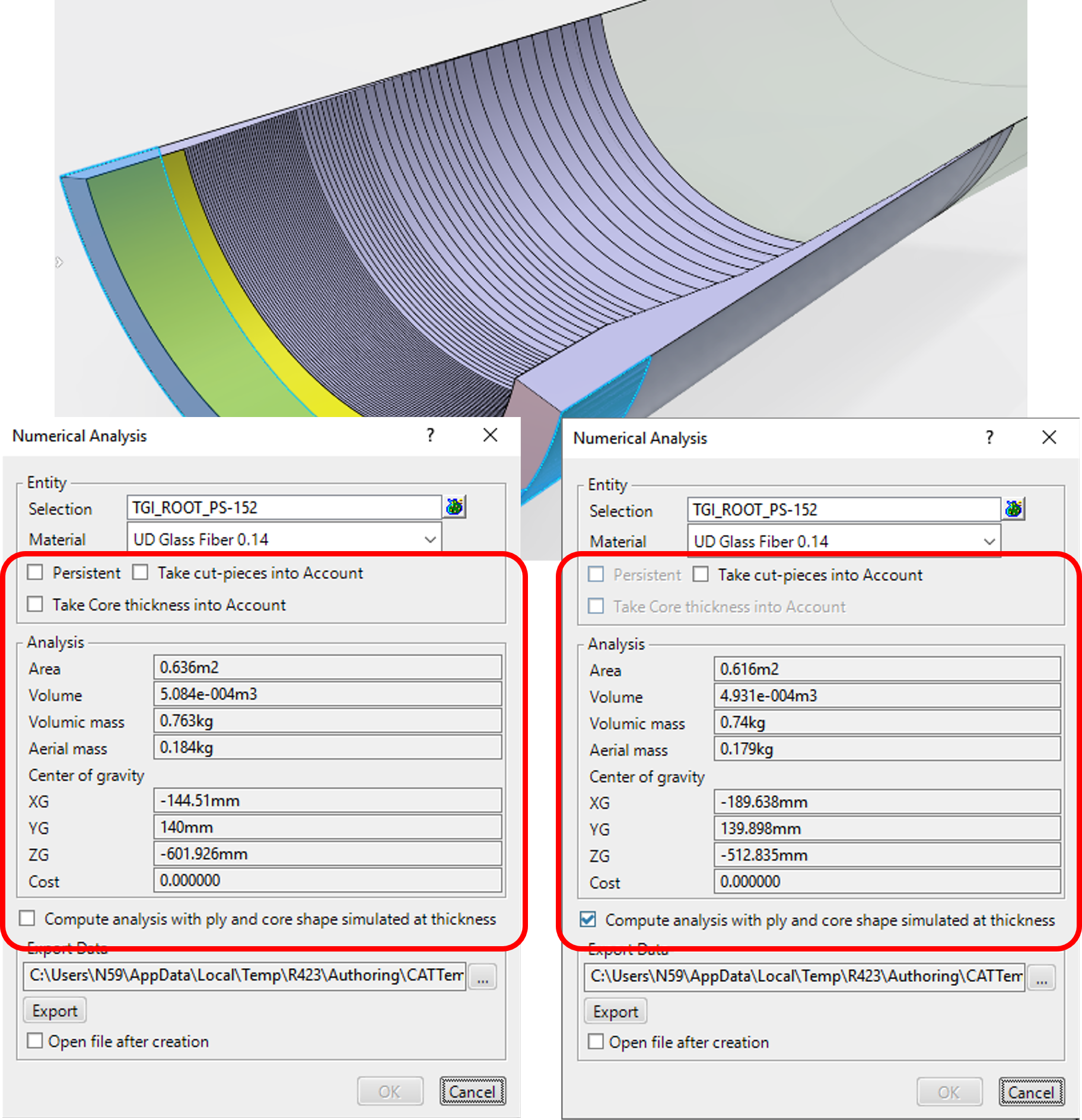
Numerical Analysis
You can now compute the analysis with ply and core shape simulated at thickness.
Grid
The command has been enhanced to solve the following issues:
- Overlapping cells when the grid panel contains reference elements tangential to each other.
- Missing cells on dome shaped parts
- Missing cells when the grid is created on a cylindrical support.
- Missing cells when the grid panel contains multi-domain reference elements.
- Missing or overlapping cells when reference elements share multiple intersections.
- Overlapping cells when the grid panel contains reference elements that are closed contours.
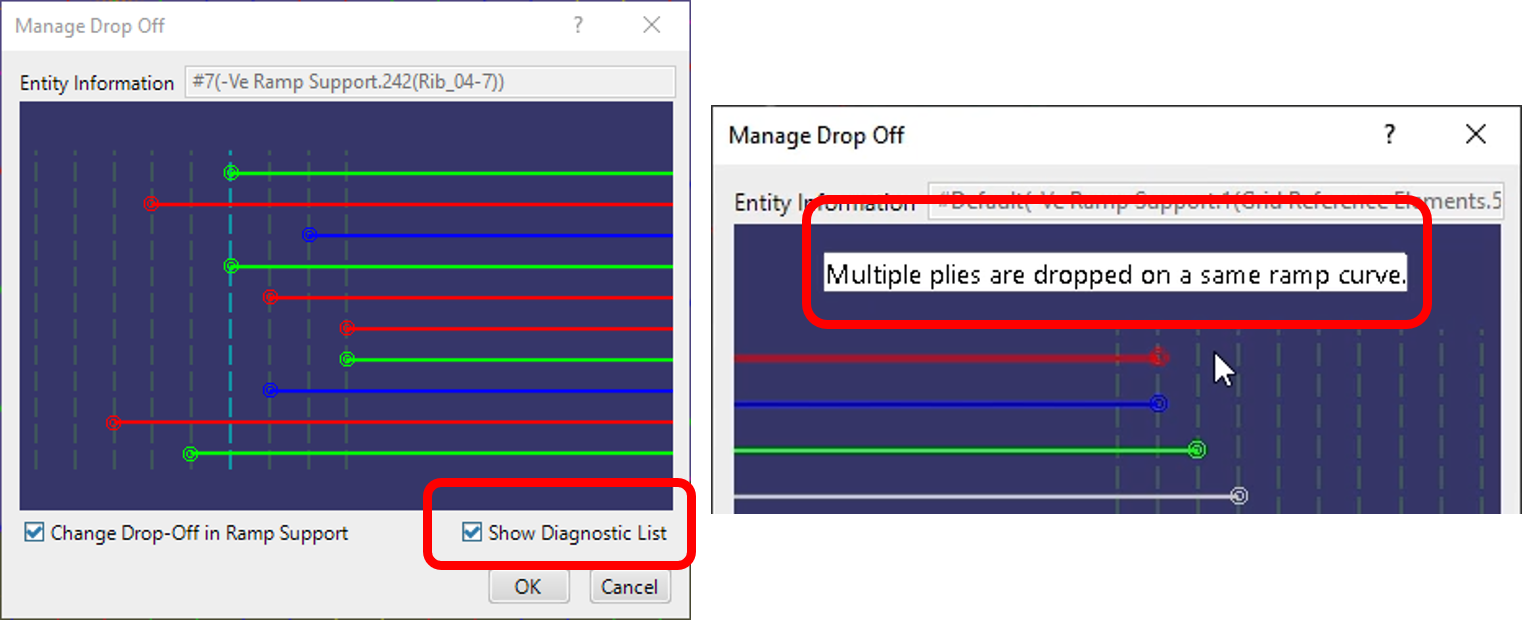
Edition of a Reference Element – 3D Visualization Mode – Virtual Stacking Drops
A check box “Show Diagnostic List” has been added to ensure a correct visualization of plies generated with the option Drop plies with same layer level on same curve.
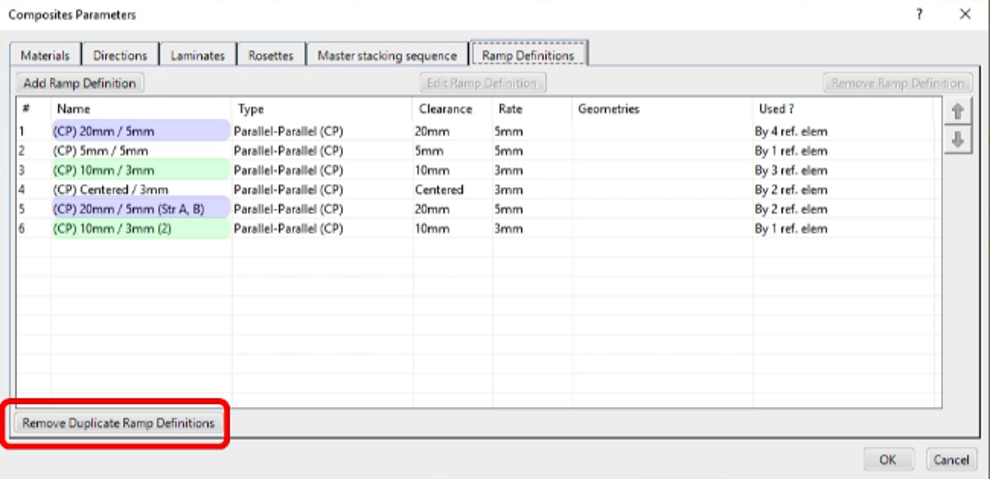
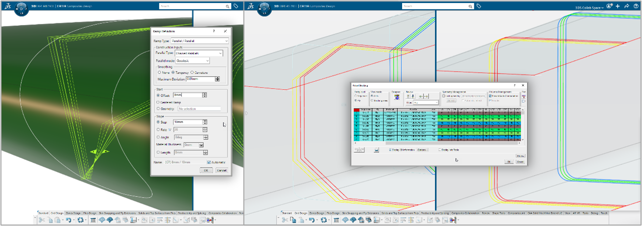
Ramp Definition
You can now automatically remove duplicate ramp definitions from the dialog box, or from a contextual menu of the specifications tree.
Staggering Edition
If edition of the reference element leads to disconnected default staggering with Centered Ramp/Centered Ramp Support type, sub-staggering’s are generated for the default segments.
When you delete generated sub-staggering’s, new sub-staggering are generated for the default segments.
Ramp Support – Between Two Curves and Angle To Curve features
Between Two Curves and Angle To Curve features are now created more robust and allow a proper selection. Use the contextual menu of the specifications tree to update groups of existing Between Two Curves and Angle To Curve features (Instead of single one).
Manage Drop Off
You can now change the drop off order of plies not generated with the Drop-off order based on layer level option.
ITA – Extended Limits
Data model has been enhanced to improve performances when modifying extension parameters of ITA Groups or creating an ITA Group with a full ply boundary as start EOP. The improvement is available on newly created or updated elements.
Solid from Iso-Thickness Areas
A check button Invert Draping Direction has been added to compute the top surface or the solid with an inverted draping direction so that the computed top surface represents the Outer Mold Line (OML). This is mainly used for plies created using Master Stacking Sequence. You need to update older features to access the check box.
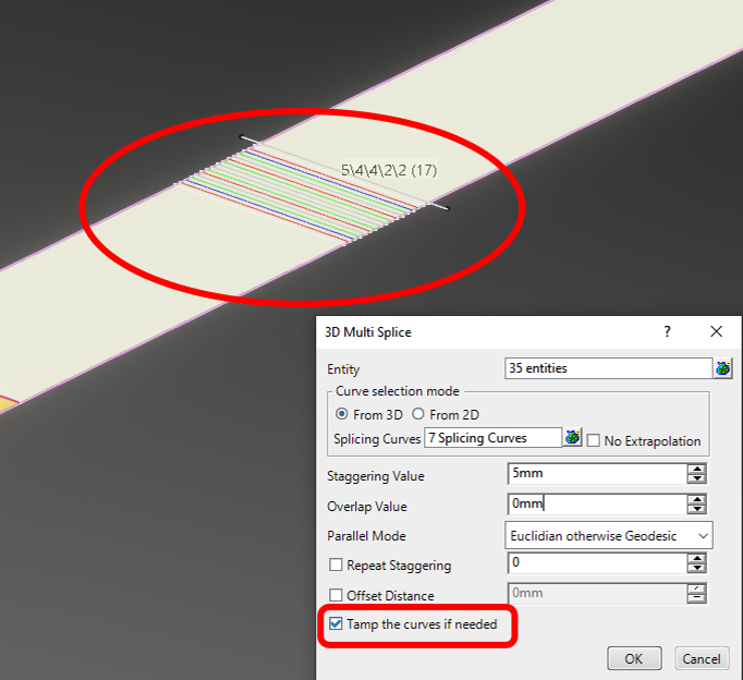
Splice Plies
The command has been enhanced as follows:
- The option Tamp the curves if needed has been added to optimize the shape of cut-pieces.
- The Parallel Mode – Parallel planes otherwise geodesic is more accurate and robust.
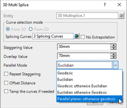
- When creating splice plies from other splice plies, the parameters of the children splice plies can now be different from the parameters of the parent splice plies.
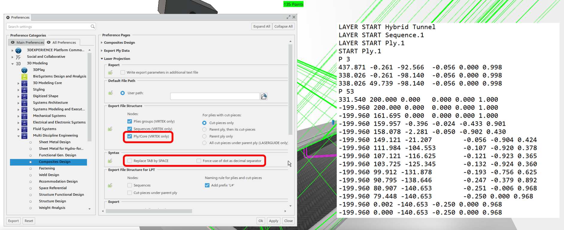
Laser Projection Export File Settings
Modifications to the VIRTEK format laser file:
- Adds layer at ply, core, cut-piece or additional geometries. It only applies to VITEK format. Plies Groups and Sequences are displayed as node in the file.
- Two options: “Replace TAB by Space” and “Force use of dots as decimal separator”
Releases: CATIA V5-6R2021 SP3 / 3DEXPERIENCE 2021x FD03
Ramp Definition: Preview of Ramp Curves and Plies
The quality of the preview of these elements has been enhanced, in particular near abrupt curvatures. However, preview for multi-domain reference element remains unavailable.
Producibility for Hand Layup
Producibility for Hand Layup has been enhanced with new propagation types and deformation models to reflect the behavior of ATL or AFP machines.
Under Propagation type:
- CFM Tape becomes CFM Tape Steering.
- CFM UD Tape producibility parameters are moved to CFM Tape Steering (They were identical and redundant).
- CFM Tape Angle is added: Principal fiber follows the theoretical direction (projected Rosette X-Axis, rotated through ply angle in plane of surface) to the edge of the ply, meaning the deviation is zero along the principal fiber.
- Both CFM Tape Steering and CFM Tape Angle support the use of a guide curve, giving an identical answer.
- Both CFM Tape Steering and CFM Tape Angle propose a Deformation Model, that can be set to Shear or Axial.
CFM FEFlatten propagation types provide now a quicker and more stable result for the flatten shape, less influenced by element and surface shape.
The new parameter Edge smoothing distance controls to which degree the material sticks to the surface.
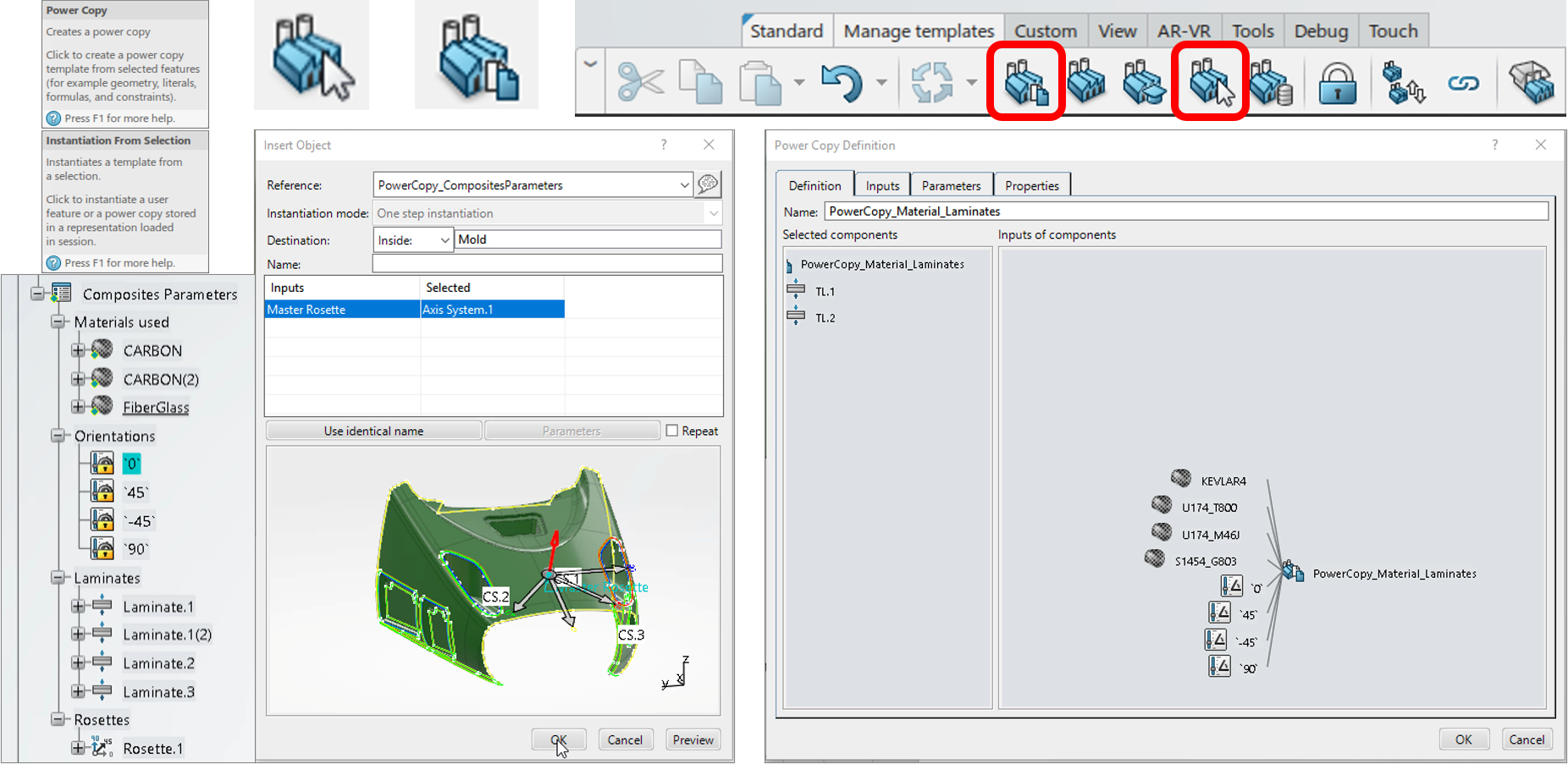
Composites Parameters
You can use Create Power Copy and Instantiate from Selection to reuse and edit Composites Parameters from a document into the current one.
Releases: CATIA V5-6R2020 GA / 3DEXPERIENCE 2020x GA
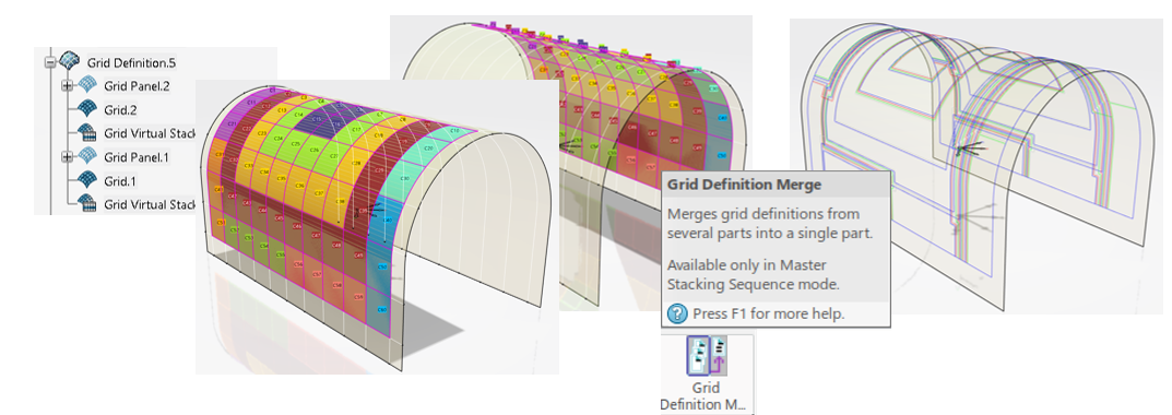
Collaborative Work
Collaborative work where you split the work on a large surface into several parts to define grids elements independently is made easier:
- Once you have completed the design on the split parts, use Grid Definition Merge to import the separate parts into an empty one.
- Create the plies groups using Plies from Virtual Stacking.
- Then use Assemble Plies Groups by Merging Plies to create one single plies group in the merged part.
- Multi-selection and plies groups option have been added to Plies from Virtual Stacking.
Import/Export Design
Both commands are now accessible independently from a flyout. Their icons have been modified.
Format Long skinny part (ex: stringers) format (4 limits & 4 offsets) has been added. This enables easy replication of same design on different shape or to re-import design after spring back compensation that modifies draping surface.
Numerical Analysis
A grid can now be taken as input.
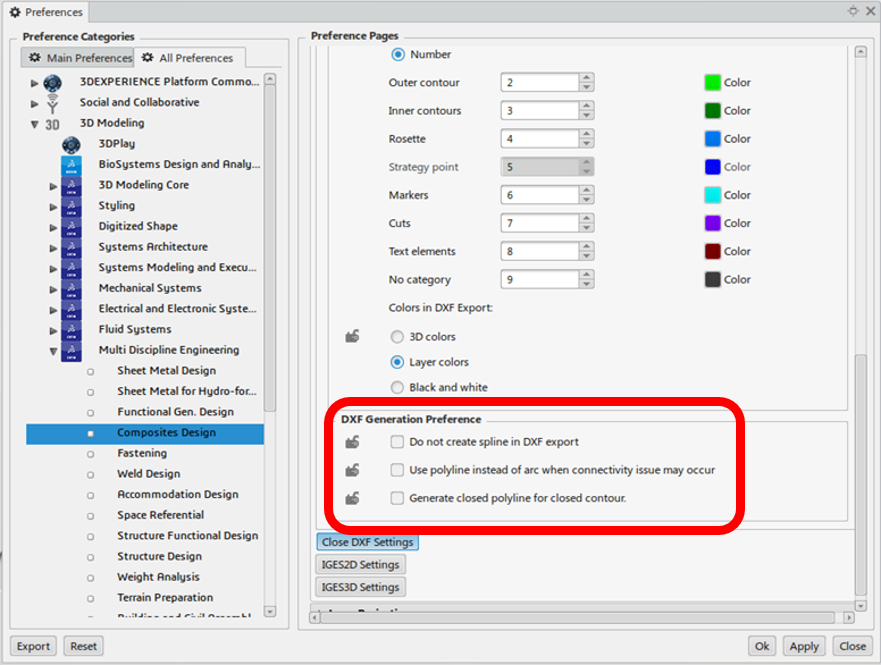
DXF Generation Preference
Three check boxes have been added to ensure exported DXF data are supported by cutting machines:
- Do not create spline in DXF export
- Use polyline instead of arc when connectivity issue may occur
- Generate closed polyline for closed contour
Questions?
If you have any questions or would like to learn more about CATIA Composites Design and Manufacturing software solutions, contact us at (954) 442-5400 or submit an online inquiry.