Reduce CAD Model Rework of Sheet Metal & Plastic Parts by 80%
If springback of sheet metal parts after stamping, or warping and shrinkage of plastic parts after injection molding, is a challenge in your manufacturing process, then like most companies you likely “just fix it on the shop floor”. This approach causes considerable rework later when product changes need to be made as there is no direct correlation between the CAD model and the final product.
Many companies go so far as to create a tooling model that is essentially a redesign of the part to compensate for the manufacturing impact on the design. However, manual methods being used to modify tooling that take into account deformations due to the manufacturing process, and control the quality of produced parts, are very labor intensive. This can require days or weeks of additional design effort, drastically increasing product development lead time and costs. It’s a good start, but there must be a better way, right?
Achieve Right Part Tooling the First Time
The answer is yes, there is a better way. Using 3DEXPERIENCE CATIA modeling software, you can automatically create a tooling model that compensates for part warping or springback in the manufacturing process. Users of this solution get the power of the CATIA modeling kernel with the ease of use of SolidWorks that the 3DEXPERIENCE user interface provides. It drastically reduces the try-out phase, ensures high-quality results, eliminating or minimizing manual finishing and tuning, and reduces overall tooling costs by 50%. Whether starting from an analysis prediction of warp/springback, or a scan of a deformed part, you can create a compensated tooling model in just one click and reduce CAD model rework of sheet metal and plastic parts by 80%.
Tooling Model Compensation – From Analysis Predictions
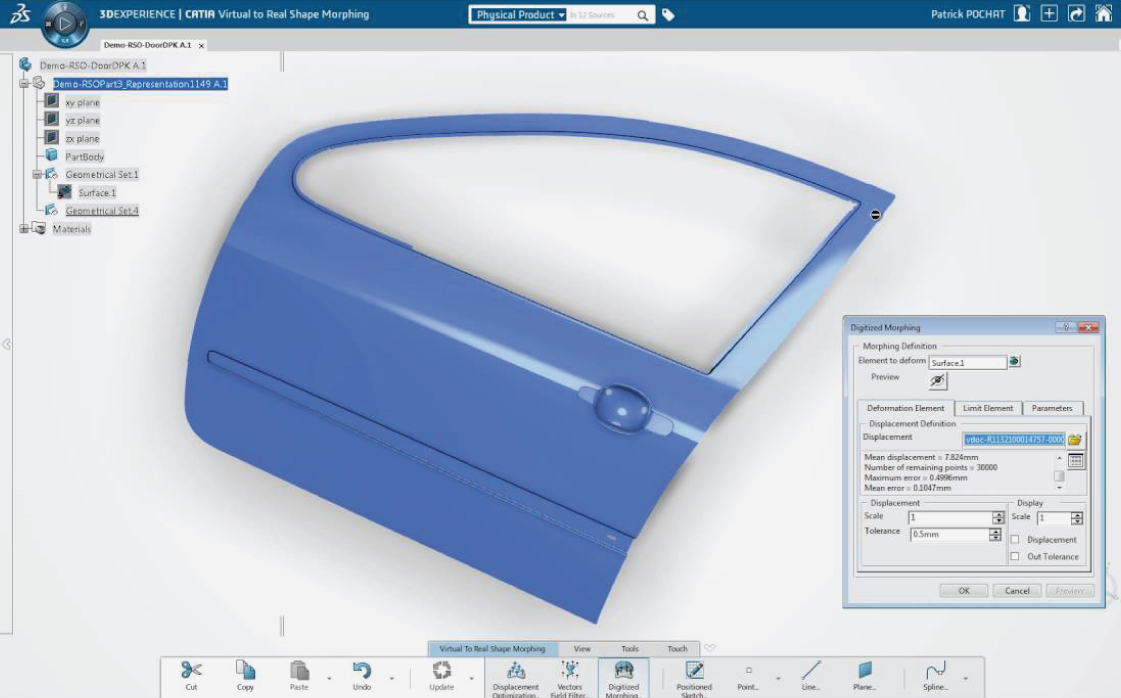
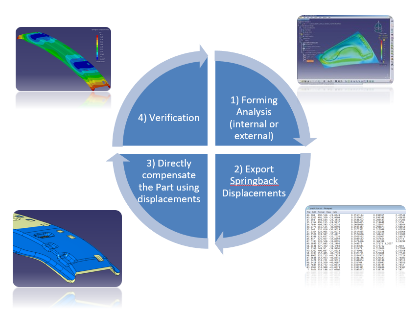
Mold flow and sheet metal forming analysis tools can produce a ‘displacements vector field’ that can be used to directly compensate the CAD model in 3DEXPERIENCE. In the image below, we start with an analysis result of the displacements (X, Y, Z, dX, dY, dZ). This is all that is needed to directly “morph” the CAD model, in one click! Users can control parameters such as the scale of deformation (for example, compensate for only 97% of prediction) or even reverse the deformation to generate the compensated tooling model.
Watch this video clip of how to achieve tooling model compensation for a sheet metal part using analysis predictions and 3DEXPERIENCE CATIA Virtual to Real Shape Morphing functionality:
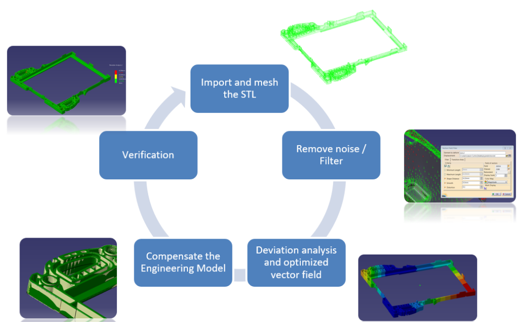
Tooling Model Compensation – From a Scanned Part
When starting from a scanned part, there are only 3 additional pre-processing steps, but the end result still provides the ability to create a compensated tooling model in one click. After importing the scanned data, 3DEXPERIENCE CATIA users can apply some quick filters to clean and repair any imperfections or isolate areas of the scan to be used for the deformation. To create the necessary displacements data for the morph operation, we simply use the Reverse Shape Optimization toolset, which measures the distance between all the nodes of the scan and the design data and generates an optimized vector field. Once you have that, it’s again a simple one-click operation to compensate the model.
Want to See It in Action?
If you’d like to learn more and get a demo of 3DEXPERIENCE CATIA, please contact us. See the significant benefits of working with these tools to ensure the quality and manufacturability of sheet metal and plastic parts.