As we know from experience with our customers, a significant number of CATIA V5 users recently installed the V5-6R2019 release. If this applies to you, this post will provide you with product enhancement highlights that capture how the release evolves the way CATIA V5 is used, allowing for better productivity, usability, and availability to smooth 3DEXPERIENCE transitions.
For quick and easy reference, we will cover release enhancements as they relate to the following areas:
- MECHANICAL DESIGN – keep scrolling to read!
- SHAPE DESIGN & STYLING – click here to view.
- MACHINING – click here to view.
Need help or have questions?
If you need help transitioning to CATIA V5-6R2019 or have questions regarding the functionality in this software release, contact our Inceptra Support experts.
CATIA V5-6R2019 Enhancement Highlights MECHANICAL DESIGN
Sketcher
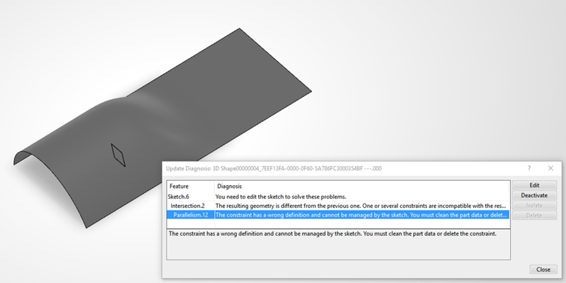
Improve use-edges error management
From the update diagnosis panel, user will be able to identify the incompatible constraint, and directly deactivate it without editing the sketch to remove the update error or replacing of this incompatible constraint by another one
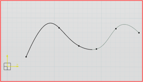
Improved trim & break visibility
Visualization of Trimmed or Break of Connect or Spline support curves are now displayed in lowlight color, with a thickness inferior to the relimited curve, and continuous linetype.
- This lowlight curve clarifies the exact shape of the spline support curve
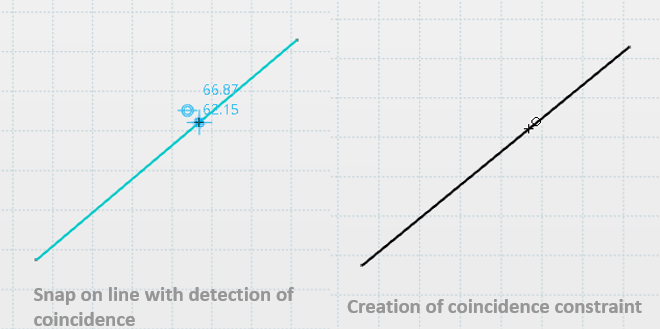
Create constraints when snapping during drag, or snapping on external edges
Automatically detect geometrical constraints when:
- Creating a geometry by snapping to external geometry (background element)
- Dragging and snapping an existing geometry to other internal/external geometry
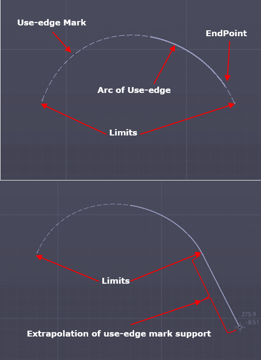
Extrapolate splines and use-edges in trim
New capability to trim a non-canonical curve use-edge mark beyond of its limits along an implicit extrapolation of its support.
User can trim an arc of use-edge outside of its limits, by dragging its endpoints along an implicit extrapolation of its use-edge mark support.
Part Design
Shaft up-to with offset
New option “Offset” capability in Shaft & Groove commands when used in “up-to” mode
- Enable users to give an offset value to the end limit
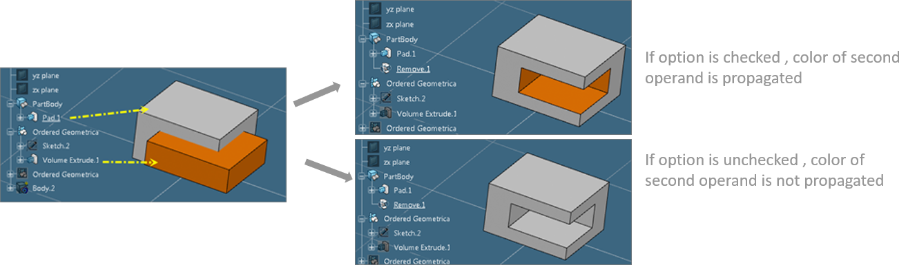
Mixed boolean operations graphics properties
Improved color management in case of mixed boolean operations.
- New option “Propagate faces to thick” is available through which all sub-elements which have tangency continuity will have same thickness/offset value
Blend corner integration in Part Design
- New command “Solid Blend Corner” added to Part Design workbench
Part Design Features Recognition
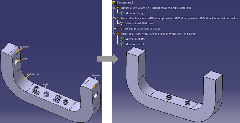
Defeaturing
New capability to support removal of chamfers and logos
- New Filters “Chamfer” and “Logo” added
- New parameters “Ignore Wall fillets” in existing fillet filter and “Depth” parameter in existing Hole filter.
Functional Tolerancing & Annotation
Support of ASME single line limit dimensions
The maximum size value of a dimension is displayed after the minimum size value when they are expressed in a single line.
- TOL_RES1 is applied as the tolerance style.
- The behavior is proposed for both ISO and ASME standards.
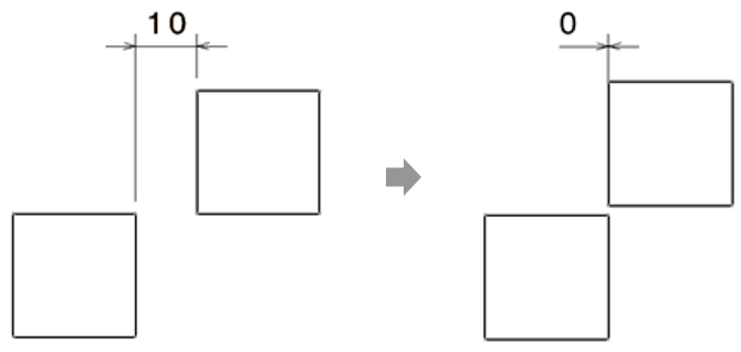
Support of dimensions with null value
- Possibility to create a valid Dimension with null value
- Possibility to keep an existing Dimension as valid when its value is modified to null value
- Automatic recognition of Dimension to be created when creation in projected mode (based on mouse over zone)
Support of text annotation frame margins
- Ability to manage horizontal margin between Text Annotation and its frame
- Ability to manage vertical margin between Text Annotation and its frame
Default property behavior managed by standard style new entries:
- Styles > Text > Default > Text > Frame > Horizontal Margin
- Styles > Text > Default > Text > Frame > Vertical Margin
New engineering symbols for various ISO standards support:
- ISO 8015:2011
- ISO 1101:2017
- ISO/TS 17863:2013
- ISO/TS 8062-2:2013
- ISO 14405-2016
- ISO 14405-3:2016
DSISO1 (true type) , SYM1/SYM2 (stroke) fonts enriched, also, new symbols automatically taken into account in:
- Geometrical Tolerance definition panel
- Dimension properties under Dimensions Texts tab-page
- Text Properties toolbar
Copy as a result with link of FTA annotation set
A dedicated option is proposed when importing an annotation set from another part. All the imported annotations are result annotations with link to the original ones:
- The result annotations cannot be edited. But their graphical representation can be modified using the Properties panel and manipulators
- They have the dedicated mask on the icon in the specification tree for synchronized/unsynchronized status
- The changes made on the original annotations are propagated to the result annotations on synchronization and update
3D leader lines
- Define Annotation leaders pointing to all geometrical elements even if annotation plane does not intersect all of them
- Dedicated options to control default leader extremity creation behavior, implying 3D leader use or not
- Add leader command providing leader creation in (2D leader) or outside (3D leader) annotation plane
- Add breakpoint command providing Z manipulator in case of 3D leader consideration
- Full support of switch between 2D and 3D leader
- Full support of 3D leader snapping
Generative Sheet Metal Design
Thread/Tap command
Thread/Tap command (from Part Design) added to workbench
- Management of both folded and unfolded views
- Management of standards (ISO, …)
- Integrated in drafting and thread analysis command

Tap-Thread analysis
Detection of threads and taps is now possible through Tap-Thread Analysis command on SheetMetal holes in both Flat and 3D views.
Composite Design
Additional contour capabilities
Support of undo/redo actions during contour creation.
- Surface selection and removal
- Curve selection and removal
- Insert option for curve selection
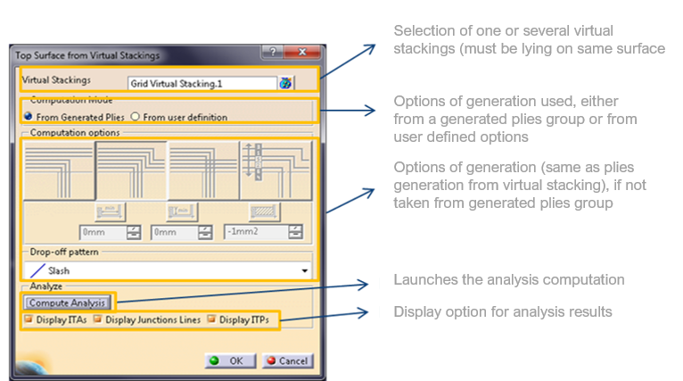
Automation of top surface from virtual stacking
New command to support the creation of top surface from virtual stacking directly.
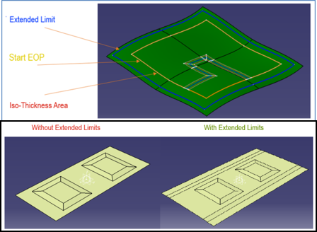
Automation of Iso-thickness area
Extended surface from Iso-Thickness Area:
- New capability to extend a top surface to a Manufacturing Edge of Part for mold creation
- Auto – User provides an “Offset value”
- User Defined – User selects Extended Limit and optionally Start EOP geometry or a contours
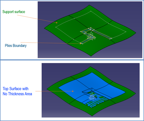
Support of No-Thickness areas to represent cutouts
- ITA can be generated with or without “No Thickness Area”
Grid panel
- Integration of “Ramp Definition objects”
- 3D Representation for Ramp based on Ramp Definition parameters are previewed
Improved stacking management
Filter Rows improvements:
- Manage filter on entity parents
- New button “Apply Filters”
- Manage Filter Rows multi selection
Ply Selection outside the Table now possible
- From 3D & Spec Tree
Enable Core Sample selection inside the table (column) and outside the table (3D viewer, Spec Tree).
New attributes Area, Length and COG (Center of Gravity) have been added on Automatic Ply Shells and Stacking Management.
Laser Projection
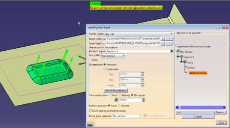
Laser projection export
Mirror option to symmetrize laser points, normal vectors and texts:
- Mirror plane (optional): field allows selection of a plane to export the mirror part
- Mirror Target Points: when a mirror plane is selected and a Laser projector is available and checked
Ability to support Ply Groups with heterogeneous support surface.

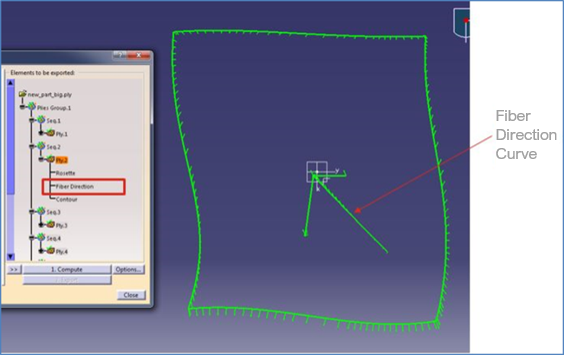
New option to include fiber direction
New option to export fiber direction for plies and cut pieces.
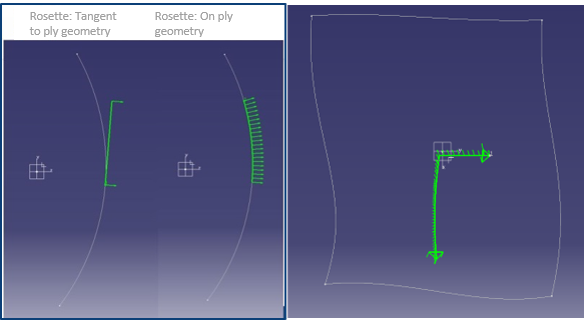
Fiber direction will be shown as a curve starting at the point where the rosette is shown and along the geometry of ply or on tangent plane.
Additional geometry on core
Additional Geometries Set can be added to a Ply or a Cut-Piece and now also to a core, in order to provide, for example, the top of the core boundary.
No change in Additional Geometries panel but Cores can be selected as father.
Support for new type of rosette which will be along the ply geometry
3 new tools/options added:
- Rosette – include rosette in laser projection export or not
- Add arrow – if checked, an arrow will be added to end of both 0 deg and 90 deg curve of rosette
- Align with fiber direction – if checked ox the exported rosette’s large curve will be aligned with fiber direction and smaller curve will perpendicular to fiber direction