Most organizations are familiar with the complexities of 3D CAD Data Management and have developed some in-house best practices or implemented a PDM tool for managing their CAD data. But once the CAD data structure is well defined and controlled, some new challenges emerge:
- How is that synchronized with the Bill of Material (BOM)?
- How do Designers and Engineers stay on the same page?
- Are you optimizing your reuse of standard parts?
- Do you need to plan for a Configured BOM, 150% BOM, Configuration Variants, Modular BOM, etc?
These questions lead companies to investigate deeper Product Lifecycle Management (PLM) functionality. This PLM approach involves creating a “single point of truth”. This is a location that contains and controls the CAD, Engineering Part and BOM data and enforces company standards and approval procedures. Let’s start with an overview of some BOM terminology and concepts.
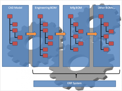
CAD and Design Data
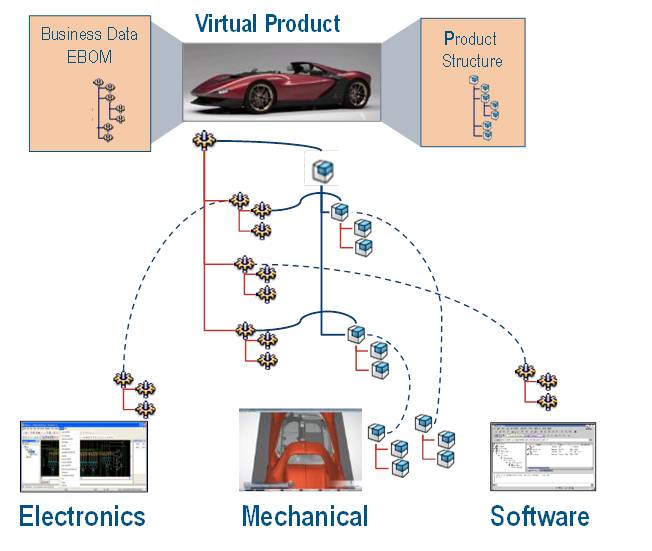
The Mechanical CAD Model Product Structure (i.e. CAD Assembly Tree) defines some of the physical requirements, but with the growing trend of combined Mechanical, Electrical and Software engineering disciplines, additional information is needed to fully define the Finished Good and complete the BOM.
Engineering Parts
Engineering Part data includes key engineering information for the object and its appropriate specifications (drawings, CAD models, etc.). This includes attributes as well as more advanced functions like Part Libraries, Manufacturer & Supplier Equivalent Parts and Alternate & Substitute parts.
Engineering BOM (eBOM)
For many companies today, the BOM data is either managed in a proprietary database or in a customized Excel spreadsheet. Maintaining the accuracy of that BOM and synchronization with the CAD data is often a manual communication process.
Manufacturing BOM (mBOM)
Once the eBOM is released, there may still be more definition necessary for multiple manufacturing locations, alternate part suppliers, regional laws or Regulatory Compliance concerns. The management of this mBOM data can be done in the PLM environment or within an ERP system. Determining how and when to communicate this information from PLM to ERP is a critical piece of the puzzle.
BOM Configurations
Many companies work on different configurations of the BOM to target different markets or to address changing requirements of the market they cater to. This requires BOM items to have unit effectivities so that they are included in the right configuration of the BOM.
Engineering Changes
A BOM change can be a nightmare if CAD and BOM files are managed in different systems. Driving a BOM change could involve changes to CAD and if there isn’t a central system tracking the latest revision of CAD and BOM, engineers could eventually enter incorrect BOM changes that carry over outdated BOM structures and CAD models. In addition, the approval process needs to be tightly controlled to ensure that only quality data is put through to the Released state.
So how do companies meet these challenges head on?
Power of Zero
The 1st step is to ensure that the CAD models generating the BOM are the latest released copy. Working with local CAD models residing on individual machines that are not in a central version controlled system could lead designers working with outdated models and hence create an inaccurate BOM.
ENOVIA V6 provides a central environment for designers to store their CAD (Mechanical and Electrical) and related data (Software, Quality Documents, etc). This is the “Power of Zero”, that is – zero local files as the relevant data resides in a central PLM repository that authorized users can access.
This PLM system also always displays the latest released revision of the CAD structure wherever it’s referenced, thus ensuring the BOM is built accurately.
Up-to-date CAD Links
When BOM data and CAD files live in unconnected systems, the integrity of the link between the BOM item and CAD entity is jeopardized every time either one changes. ENOVIA allows users to generate the BOM from the right CAD with just a single click of the button using the EBOM Sync. This action also links that version of the CAD to the BOM. Now every time a change is made, it is easy to see the design impact and understand the downstream effect of the changes.
Collaboration
When CAD and BOM data are synchronized and the release process is controlled by an electronic system, the likelihood of BOM errors drops significantly. Users are more aware of their co-workers actions and have better visibility to upcoming changes and potential risk factors.
To learn more about ENOVIA V6, please contact your local
Inceptra Account Manager or send a request to info@inceptra.com